Setting up a paper mill plant is an engineering project, not a purchase. A paper mill facility, whether a compact mill or a large paper mill industrial plant, runs well for thirty years or not depending on decisions fixed early: site survey, mass balance, plant layout, civil foundations, equipment sequencing, piping and utilities, installation, commissioning. Get any one of those wrong and the machine cannot recover the difference in trim speed or yield.
This guide walks through the layout, process flow, engineering design, and installation workflow Parason uses on projects from 8 TPD mini mills to 1,200 TPD integrated lines across 75+ countries. For the business and cost side of setting up a mill (capacity bands, investment ranges, payback), see our paper mill plant guide.
Paper mill plant setup: scope and sequence
Setting up a paper mill follows a six-step sequence: choose grade and capacity (TPD), select site by water/power/fibre/logistics, design plant layout in 2D and 3D, size equipment against a mass balance, route piping and electrical via P&ID, then erect and commission. Steps 3 to6 are the engineering phase where most project risk concentrates.
A paper mill is a continuous process plant made of four zones: stock preparation, the wet end of the paper machine, the dry end, and the auxiliary systems. Fibre enters as bales, rolls, or chips, and leaves as a finished reel. Stock prep cleans and refines the fibre. The wet end (headbox, forming, press) turns slurry into a wet sheet. The dry end (drying cylinders, calender, reel) finishes and winds it. Auxiliary systems (water circuit, steam, power, compressed air, ETP, sludge handling) keep the machine running.
Setting up the mill means deciding, in order:
- What paper grade and capacity (TPD) you will produce.
- Where the mill will sit, based on water, power, fibre availability, and logistics.
- What the plant layout looks like in 2D and 3D, including civil foundations and steel structure.
- Which equipment goes where, sized against a mass balance.
- How piping, electricals, and controls connect every vessel and motor on the P&ID.
- How the mill is erected, commissioned, and ramped to rated capacity.
Steps 3 to 6 are the engineering phase. That phase is where Parason's in-house design team and ABB automation partnership do most of the work. Most project risk concentrates here, which is why basic and detail engineering are bundled into Parason's Concept to Commissioning scope rather than left to the customer.
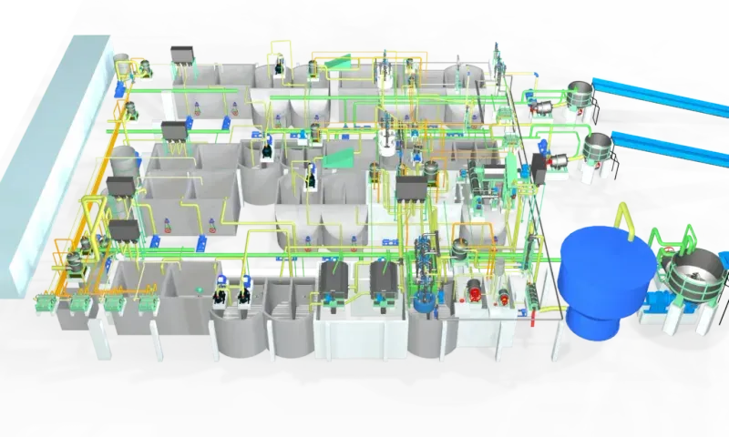
Paper mill plant layout and process flow diagram
A paper mill process flow diagram shows three sections in series: stock preparation (pulping, cleaning, screening, refining), the paper machine (approach flow, headbox, wire, press, dryers, reel), and auxiliary systems (white water, steam, ETP). Unit operations are identical from 30 TPD to 1,000 TPD; only equipment size and parallel-line count scale up.
The paper mill process flow diagram is the spine of the plant layout. Every downstream design, civil, piping, electrical, instrumentation, flows from it. A paper mill block diagram and a detailed paper mill schematic deliver the same information at different zoom levels: the block diagram shows unit operations, the schematic shows flow paths, valves, and control points.
A typical recycled-fibre paper mill flow diagram looks like this:
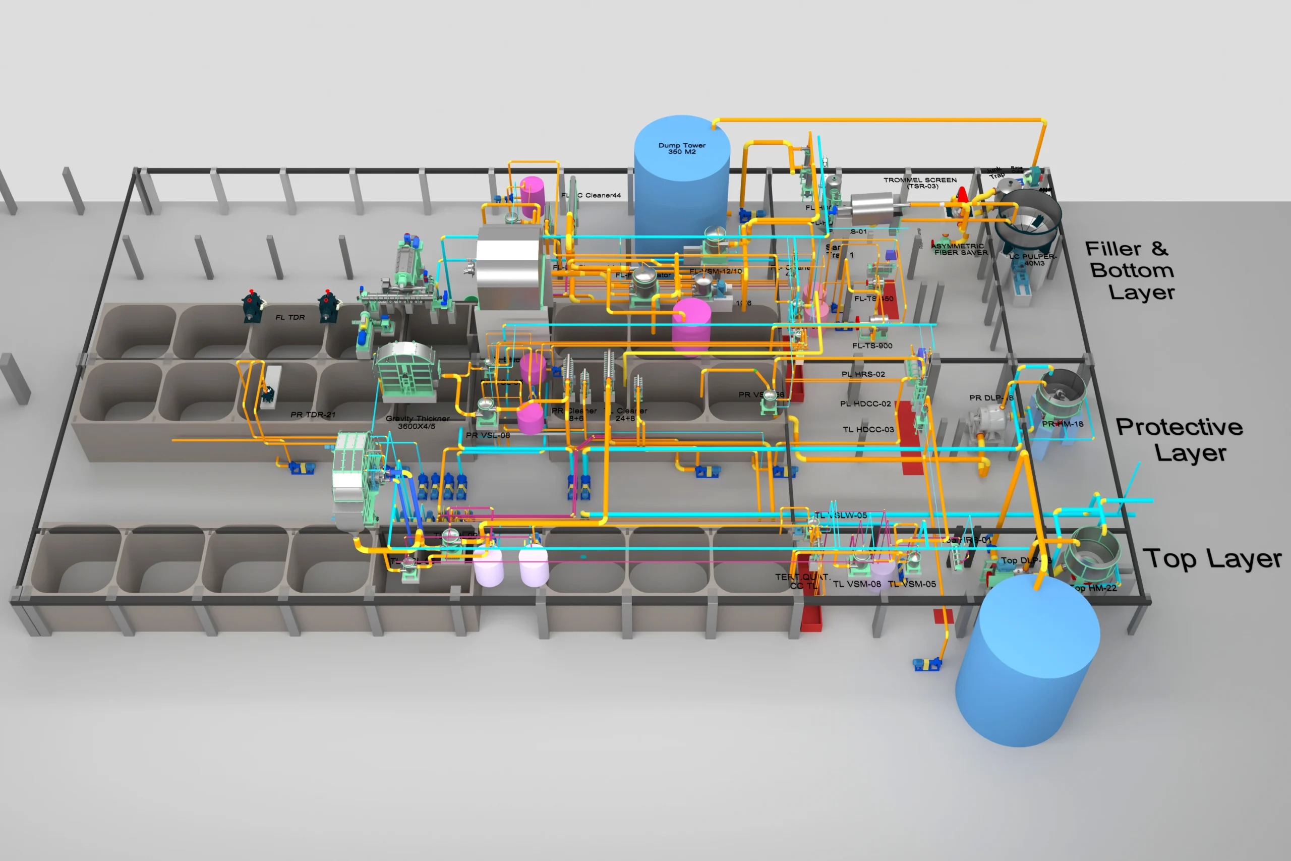
- Stock Preparation: Bale Breaker → Drum/HC Pulper → Dilution → HD Cleaner → Coarse Screen → Fine Screen → LC Cleaners → Thickener → Dispersion → Refiners → Machine Chest.
- Paper Machine: Approach Flow → Headbox → Wire Section → Press Section → Pre-Dryer → Size Press → After-Dryer → Calender → Reel → Winder.
- Auxiliary: Broke Handling → White Water Circuit → Fresh Water → Chemical Dosing → Steam & Condensate → Vacuum → Compressed Air → ETP → Sludge Handling.
This sequence is the industrial paper making process at its simplest: the same unit operations run inside a 30 TPD paper mill and a 1,000 TPD paper mill, with more parallel lines and larger equipment rather than fundamentally different steps. For virgin-fibre and agro mills, the front end changes: debarking and chipping (wood) or depithing and continuous digester (straw, bagasse, sarkanda) replace the pulper, followed by brown stock washing, oxygen delignification, and ECF bleaching before the stock enters the approach flow. The pulp mill process flow diagram sits upstream of the paper machine process flow diagram; together they form the pulp and paper mill process flow diagram for an integrated plant.
The paper making process flow becomes the paper mill diagram (2D layout) once equipment footprints, elevations, and connections are overlaid on the plot plan. A paper making diagram, a paper plant diagram, and a paper mill process diagram are different names for the same engineering deliverable at different levels of detail. Parason's basic engineering package includes the P&ID, 2D and 3D layouts, equipment lists, pump and motor lists, and piping isometrics for the paper mill paper machine diagram set.
Plant layout principles: stock prep to reel
Four principles drive a clean paper mill layout: gravity flow for stock chests and white water (saves 8 to12% of pumping energy), short straight pipe runs from machine chest to headbox, hot/wet zones separated from electrical rooms (MCCs on the cold side), and maintenance space designed in for refiner, screen, and dryer changes.
Four principles decide a clean paper mill layout. These principles apply equally to a paper factory layout, a pulp mill layout, and an integrated paper mill layout plan.
Gravity flow where possible
Stock chests are elevated so that dilution and transfer happen with minimal pumping. Pulpers sit one floor above the coarse cleaner. White water silos are placed above the approach flow pumps. Pumping energy on a mid-sized mill is 8 to 12% of total power demand; layout can move that figure by two or three points.
Short, straight pipe runs at critical points
The approach flow from machine chest to headbox and the white water return from save-all to silo are the two runs that most affect machine performance. Parason standardises these runs at minimum elbows, with flow conditioners before the headbox feed pump.
Hot and wet zones separated from electrical rooms
Dryer hoods, steam headers, and condensate tanks produce heat and humidity that attack switchgear, VFDs, and control cabinets. MCC rooms sit on the cold side of the building, with sealed cable trenches and positive pressurisation.
Maintenance space designed in, not bolted on
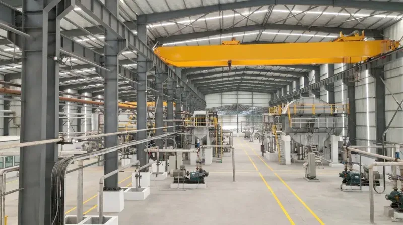
Refiner disc changes, screen basket changes, press felt runs, and dryer can repairs all need crane coverage and pull-out space. EOT crane spans, monorails above pulpers, paper machine walkway widths on both tending and drive sides, and pull-out zones for press rolls are decided at the 3D layout stage.
Parason's 3D layouts are reviewed against clash detection on piping, cable trays, and structural steel before civil drawings are released. Catching a clash on screen is cheap; catching it during erection costs a week and a dozen cuts.
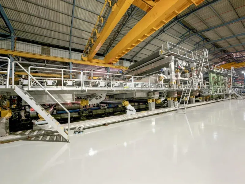
Paper machine room design and foundation
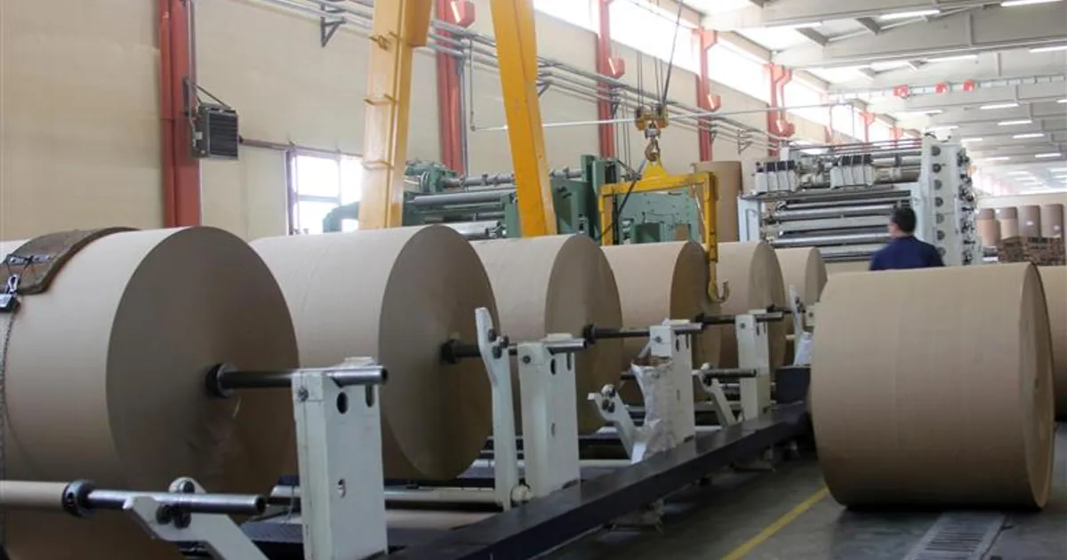
The paper machine foundation is a single mass of reinforced concrete 1.2 to2.5 m deep, sized for dynamic loads above static weight, with vibration isolation joints separating it from the building structure. A 3.0 to4.5 m basement houses press save-alls, broke pulper, and white water silo for mills 50 TPD and above.
The paper machine room is the most civil-intensive part of the paper mill design. Two decisions drive the paper machine design at the room level: foundation geometry, and basement depth. Headbox design (hydraulic vs air-cushion, slice lip geometry, turbulence generator layout) and dryer hood design (closed hood vs open, heat recovery loops) are handled separately in the machine engineering package, but their loads and clearances are anchored in this room design.
Machine centreline and tending side
The machine foundation is a single mass of reinforced concrete, typically 1.2 to 2.5 m deep depending on machine speed and deckle, with dynamic loading margins above static weight. Vibration isolation joints separate the machine foundation from the building columns so that the paper machine does not shake the roof or vice versa.
Basement depth for press and dryer pits
Press section save-alls, couch pit, broke pulper, and white water silo sit below machine floor level. A 3.0 to 4.5 m basement with graded floors and sump pumps is standard for 50 TPD and above. Mini mills below 30 TPD can run with a shallower 2.0 m basement and bolted-down save-alls.
Dryer section foundation takes the steam header, condensate return manifolds, and siphon pipework. Parason's detail engineering pack covers foundation drawings, load details at each pedestal, and nozzle orientations for every vessel and pump.
Layout considerations by capacity: 8 TPD to 1,200 TPD
Plant footprint scales from 2 to4 acres (8 to 30 TPD mini mill, single HICON pulper, 1.4 to2.1 m deckle Fourdrinier) up to 25 to40+ acres (800 to1,200 TPD, drum pulper or LCO-145, twin-wire former, 6.7 to8.5 m deckle, shoe press). Equipment selection changes band-by-band; the same unit operations exist at 10 TPD and 1,000 TPD.
Plant layout scales in two ways: more equipment at higher capacity, and different equipment selections at different capacity bands. The same unit operations exist at 10 TPD and 1,000 TPD, but the pulper model, cleaner cascade depth, former type, press configuration, and machine deckle all change band by band. Selecting correctly at design stage avoids the two most expensive mistakes: buying mini-mill equipment for a scaling project, or buying large-mill equipment where mini-mill throughput would suffice.
The reference table below summarises equipment selection and land footprint across five capacity bands Parason typically engineers. Pulper models cited are catalog-verified and link to their equipment pages; exact kW and TPD are chosen based on fibre type, target machine speed, and mill availability targets during basic engineering.
| Capacity band | Footprint | Stock prep layout | Machine section |
|---|---|---|---|
| 8 to 30 TPD (mini) | 2 to 4 acres | Single HICON pulper (HM-3 to HM-8, 90 to 180 kW), compact screen and cleaner line | Single-wire Fourdrinier, deckle 1.4 to 2.1 m, speed 150 to 300 m/min |
| 50 to 100 TPD | 4 to 8 acres | HICON pulper: HM-10 (50 to 65 TPD, 200 kW), HM-12 (65 to 80 TPD, 220 kW), or HM-15 (80 to 100 TPD, 325 kW); two-stage screening | Fourdrinier or Crescent tissue, deckle 2.5 to 3.6 m |
| 150 to 300 TPD | 8 to 15 acres | Drum pulper PDP-15 to PDP-30 (132 to 250 kW), full cascade: 3 HD cleaner stages, 3 screen stages, 6 LC cleaner stages | Multi-wire or hybrid former, deckle 3.6 to 5.2 m |
| 400 to 600 TPD | 15 to 25 acres | Drum pulper PDP-45 or PDP-60 (400 to 560 kW), parallel stock lines for white and brown, deinking plant | Gap former or top-wire former, deckle 5.2 to 6.7 m |
| 800 to 1,200 TPD | 25 to 40+ acres | Drum pulper PDP-80 or PDP-100 (800 to 1,000 kW) for 800 to 1,030 TPD, or LCO-145 (1,000 kW) for 1,100 to 1,300 TPD; dedicated virgin and secondary fibre lines, oxygen delignification | Twin-wire former, shoe press, deckle 6.7 to 8.5 m |
Parason has installed turnkey mills across this full range, including kraft, duplex board, tissue, writing-printing, and linerboard paper machine lines. Reference projects include Viking Kait (50 TPD tissue), Quantum Papers Nigeria (300 TPD kraft), Diyan Papers (300 TPD duplex and 350 TPD kraft), Ambani Paper (400 TPD duplex), and Sedy Egypt (220 TPD kraft).
Land requirement is a common first question. The indicative footprints above include stock prep, machine hall, finishing, ETP, sludge yard, raw material storage, finished goods warehouse, roads, and utility block. Indian MSME projects on compact plots (2 to 3 acres for mini mills) achieve the same throughput with vertical stock prep towers and integrated chest designs.
Paper mill location selection criteria
Five factors decide a viable paper mill site: reliable water (8 to15 m³/t recycled, 40 to80 m³/t agro), reliable power (3 to5 MW per 100 TPD, 15 to25 MW per 500 TPD), fibre access within economical transport radius, outbound logistics to converters or ports, and effluent discharge compatibility with local environmental norms.
Site selection is an engineering decision before it is a commercial one. Five factors decide whether a site is viable.
Water availability
A recycled-fibre mill uses 8 to 15 m³ of fresh water per tonne of paper after closure. A virgin agro mill uses 40 to 80 m³. These ranges align with industry-wide water-intensity benchmarks published by the Confederation of European Paper Industries (CEPI). Groundwater, river intake, or treated municipal supply must all be tested for hardness, TDS, iron, and biological load before site commitment. Hard water adds softening cost every day of the mill's life.
Power availability and reliability
A 100 TPD mill draws 3 to 5 MW. A 500 TPD integrated mill draws 15 to 25 MW. Grid reliability, tariff structure, captive power feasibility, and waste-heat recovery potential all factor in. Parason's electrical engineering package covers HT and LT switchgear, motor control, VFD schedules, and cable lists for both grid and captive scenarios.
Fibre and raw material access
Wastepaper collection radius, imported kraft pulp port distance, or agro residue (bagasse, wheat straw, sarkanda) catchment area. Transport cost of fibre is typically 3 to 7% of production cost; a badly located mill never recovers this gap.
Logistics and market accessibility
Finished paper is bulky. Outbound road and rail connections to converters, packaging plants, or ports decide the effective market radius.
Effluent discharge and environmental clearance
Treated effluent discharge norms, sludge disposal routes, and green-zone restrictions vary by country and state. The ETP footprint must fit the site, not be squeezed later.
Parason has advised on location selection for mills in Nigeria, Bangladesh, Vietnam, UAE, Saudi Arabia, Indonesia, Egypt, and Brazil, each with different water, power, and raw material constraints.
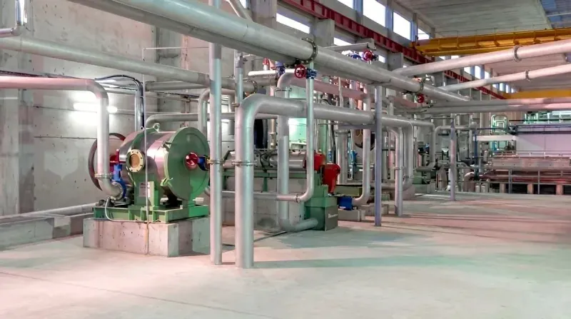
Utilities layout: steam, power, water, compressed air
Utilities consume 40 to55% of a paper mill's operating cost. Steam (1.4 to2.2 t per tonne of paper) routes from boiler house upwind via overhead pipe racks, with gravity-first condensate return. Power steps down at the receiving substation to 6.6 or 11 kV; MCC rooms sit close to load centres. The white water loop is the single most layout-critical utility.
Utilities are 40 to 55% of a paper mill's operating cost. Layout decisions here pay back for decades.
Steam
Dryer section steam demand is 1.4 to 2.2 tonnes of steam per tonne of paper for standard grades, higher for tissue — ranges that line up with the energy-intensity benchmarks documented by the FAO global pulp and paper sector study. Boiler house sits upwind of the machine hall, with main steam header routed on overhead pipe racks. Condensate return is gravity-first, pumped only where unavoidable. Flash steam recovery from condensate and blow-down is built in at design, not retrofitted.
Power distribution
Main receiving substation steps grid HT down to the plant distribution voltage (6.6 kV or 11 kV for larger mills, 415 V for smaller). MCC rooms are placed close to load centres to minimise cable runs. VFDs for refiners, pulpers, and machine drives are specified by Parason's electrical team during detail engineering.
Water circuit
The white water loop is the single most important utility in a paper mill. Save-alls, white water silos, fresh water towers, and chemical dosing points must all connect cleanly. Fresh water intake and ETP discharge are on opposite sides of the plant to avoid cross-contamination.
Compressed air
Instrument air (dry, oil-free, for valves and DCS) is separated from plant air (for cleaning, pneumatic actuators). Compressor room sits adjacent to the power substation.
Auxiliary systems: sludge handling, ETP and material flow
ETP runs in three stages: primary (flotation, clarification) removes suspended solids, secondary (biological) removes BOD/COD, and tertiary (filtration) meets discharge norms. Sludge dewaters from 2 to3% to 25 to28% via belt filter or screw press, then routes to boiler fuel, cement co-fuel, engineered landfill, or Bio-CBG conversion.
Paper mill auxiliary handling is where many projects lose schedule and budget. The sludge yard, ETP, and material flow network need engineering attention equal to the main process.
ETP staging
Primary treatment (flotation, clarification) removes suspended solids. Secondary (biological) removes BOD and COD. Tertiary (filtration, polishing) meets discharge norms. Parason's ETP equipment range covers the full train: rotary drum screens, flotation cells, conventional clarifiers, and polishing filters, each sized to mill capacity and raw material.
Sludge dewatering
Belt filter presses and sludge screw presses take sludge from 2 to 3% consistency up to 25 to 28% outlet, depending on machine selection and sludge characteristics. Dewatered sludge either goes to the boiler as fuel, to cement plants as co-fuel, or to engineered landfill. The Bio-CBG option (Parason's KIS Group partnership) converts sludge and organic effluent to compressed biogas.
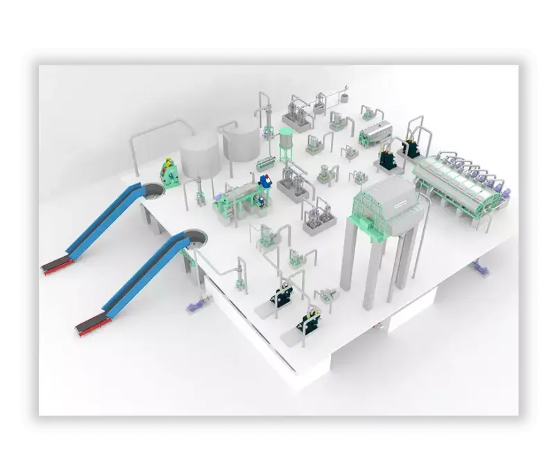
Material flow
Bale yard to pulper, broke to broke pulper, finished reel to winder to warehouse: every conveyor, forklift path, and truck turning circle is drawn at the 3D layout stage. A mill that needs three forklift moves for one raw material unload is bleeding labour cost every shift.
Paper machinery installation and commissioning workflow
Greenfield paper machine installation runs 8 to14 months across eight phases: engineering kickoff, mechanical erection, piping, software FAT, cold IO check, hot IO check, start-up and ramp to design speed (2 to6 weeks), then post-commissioning process optimisation. Foundation handover marks the start; first reel marks commissioning complete.
Installation is not unloading crates and bolting them down. It is a sequenced schedule of mechanical, piping, electrical, and commissioning activities, typically 8 to 14 months on a greenfield project. Paper machine installation runs in parallel with pulp mill installation on integrated projects.
Parason's supervision of erection and commissioning follows eight phases:
- Engineering meeting to align site team, civil contractor, and Parason engineers on drawings, sequence, and milestones.
- Mechanical erection. Foundations handed over, equipment received, crane plan executed. Pulpers, cleaners, screens, refiners, machine sections set on baseplates and grouted.
- Piping erection. Process piping, steam, condensate, fresh water, white water, chemical lines, instrument air. Hydro-testing and flushing before commissioning.
- Software FAT. DCS programs, HMI screens, control loops tested at factory or offline before site integration.
- Cold IO check. Every input and output signal verified from field device to DCS tag without process running.
- Hot IO check. Signals verified with motors energised and valves stroked, water running in selected sections.
- Start-up and commissioning. Wet end fill, first stock to wire, first sheet on reel. Ramp from minimum stable speed to design speed over 2 to 6 weeks depending on grade.
- Process optimisation. Fibre loss, energy consumption, breakdown intervals tuned during the first quarter of operation. Parason offers post-commissioning audits (refining, screening, complete stock prep, paper machine) to lock in the gains.
Pulp mill installation within integrated plants
Integrated mills run pulp mill installation in parallel with paper machine erection for 4 to6 months, converging at the pulp storage tower. Wood mills use vertical batch digesters with multi-hour cooks; agro mills (50 to 300 TPD bagasse, straw, sarkanda) use depithing, continuous digester, brown stock washing, oxygen delignification, and ECF bleaching.
An integrated mill produces its own pulp and its own paper. For wood-fibre mills, that means a complete pulp mill upstream of the paper mill: debarking, chipping, screening, cooking, washing, oxygen delignification, and ECF bleaching. For agro mills, depithing, continuous digester cooking, brown stock washing, and bleaching. Pulp mill installation runs in parallel with paper machine installation on integrated projects, and the pulp mill diagram sits upstream of the paper machine installation plan in the master schedule.
Parason's agro pulping turnkey solutions cover 50 TPD to 300 TPD for wheat straw, bagasse, rice straw, and sarkanda. The process runs a dry depithing system, wet washing pulper, continuous digester, counter-current brown stock washing with weak black liquor recovery, pressure and vibrating screens, oxygen delignification reducing Kappa number, and ECF bleaching with chlorine dioxide, hydrogen peroxide, oxygen, and caustic.
For wood pulping, vertical batch digesters cover the full capacity range and run multi-hour cooking cycles tuned to species and furnish. Raw materials include eucalyptus, casuarina, subabul, acacia, and bamboo. The pulp mill installation sequence runs parallel to paper mill installation for 4 to 6 months, then converges at the pulp storage tower and approach flow.
Common plant engineering challenges and how to design them out
Five challenges recur on most projects: capacity mismatch between stock prep and machine (size stock prep at 110% of machine capacity), white water loop instability (closed-loop dissolved-solids accumulation), refiner energy swings (centralised refining cuts 26 to30% power), drying bottleneck (under-sized dryer caps throughput forever), and ETP load surprise (mixed-grade mills exceed textbook predictions).
Five challenges come up on almost every project. Each has a known engineering answer.
Capacity mismatch between stock prep and paper machine
If stock prep is sized for 110% of machine capacity, the mill is reliable. If sized for 95%, every break starves the machine. Mass balance at design stage is where this is fixed.
White water loop instability
A closed water system accumulates dissolved solids and fines. Save-all efficiency, fresh water makeup points, and chemical dosing sequence all need to be designed together, not left to operator trial.
Refiner energy swings
Decentralised refiners at multiple consistency stages can consume 200 to 350 kWh per tonne — consistent with the refining specific-energy ranges documented in TAPPI standards and technical literature. Centralised refining in a single optimised stage has shown 26 to 30% power reduction in Parason case studies. The layout has to support that choice.
Drying bottleneck
Dryer section is the most expensive part of the machine. Under-sizing costs throughput forever. Oversizing costs capital. Steam balance, cylinder count, and hood design are sized against grammage range at design.
ETP surprise
Effluent load estimates based on textbook values commonly under-predict real loads on mixed-grade mills. Parason designs ETP with headroom on primary and secondary capacity, plus a polishing stage that can be upgraded later without plant shutdown.
Parason's R&D lab (SEM, fibre analyzer, paper testing, spectro lab, pilot mill) supports design decisions with real fibre data, not catalogue assumptions. CFD simulation during design shows headbox flow, white water flow, and dryer hood air patterns before the equipment is built.
Next steps
If you are scoping a new paper mill project, a capacity expansion, or a grade change retrofit, the starting point is a mass balance and site survey. Parason teams have supported paper mill setup and paper mill plant projects, from a small paper processing factory of 8 TPD to a 1,200 TPD papermill factory complex, across every major production grade. Parason offers project audits, refining system audits, screening audits, complete stock prep audits, and paper machine audits as standalone services, or bundled into the basic engineering phase of a turnkey project.
For the business case, investment bands, and ROI framework, see our paper mill plant cost and setup guide. For grade-specific machinery selection, see kraft paper mill machinery, tissue paper production line, and top paper mill machinery manufacturer in India. Explore stock preparation, paper machine, tissue machine, and agro and wood pulping equipment ranges for full specifications.
To discuss a specific project, contact the Parason engineering team.